


Page 54 - TFC 2022 Catalogue
P. 54
FAQ’s


           Connection of WiFi devices to 5GHz WiFi router:
           Many WiFi products – including Optimum WiFi devices – are configured to use the long-established 2.4GHz WiFi frequency.  Since 2016, some new WiFi routers come with both
           5GHz & 2.4GHz, with a single SSID set with a shared name. WiFi devices can connect with the 5GHz network if close to the router, or the 2.4GHz network if further away – 5GHz is
           faster but has a reduced range compared to 2.4GHz. Most routers will have a configuration set to use 5GHz as the preferred connection. If you try to connect to an Optimum WiFi
           device and can’t (the connect function goes full circle and then fails), your mobile may be connected to the 5GHz network. You will need to go into the Admin page of the router. You
           may need to refer to the router documentation, or contact your service provider for help with this. Separate the channels and re-name the 2.4GHz/5GHz networks with different names
           e.g. add 2g or 5g to the end of each SSID respectively. Re-connect your phone to WiFi, selecting the re-named 2.4GHz network. You should now be able to set up the WiFi controls in
           the usual fashion.
           Once the WiFi controls are set up in this way, control of WiFi devices is possible whether the mobile is connected to 5GHz or 2.4GHz. That’s because the input from your mobile is
           actually sending data to the server, which is then relaying the control commands or programming changes back to the WiFi device via your router, and because the WiFi router is
           dual-band, it can address devices connected to either the 5GHz or 2.4GHz networks.
           If this fails, please check your Firewall settings have no security features enabled to prevent new devices connecting. You may need to refer to the router documentation, or contact
           your service provider for help with this.
           Volt-free switching:
           A thermostat or timer with ‘volt-free contacts’, or ‘volt-free switching’, operates a switch that opens and closes its contacts, but no voltage or current will flow.� When a product has
           volt-free contacts, the installing electrician�must�ensure that the correct voltage (to be switched) is connected to the ‘common’ contact of the switch.� This voltage, once connected to
           common, will then be fed to the circuit to be controlled, via the normally open contact.� Wiring connected to the common contact must be suitably rated for the load current.� The
           advantage of such an arrangement is that e.g. a�mains-powered timer can switch a non-mains circuit, such as a low voltage alarm or lighting circuit.
           Switching lighting loads:
           Lighting can be a problematic load because of very high inrush current compared to the running current requirement.  This particularly applies to high efficiency fluorescent, and
           other types of HID lamps as well as LED lighting.  This is because these types of luminaires frequently have starter gear or a transformer that uses power factor correction on the
           start-up circuit. This can cause an inrush current that is hundreds of times higher than the running current and overloads the contacts. Although this may only exist for 5 or 10
           milliseconds, it is enough time to tack weld the output contacts. If you are connecting a timer to a lighting load you may need to switch the lighting circuit with a contactor.  If in doubt
           contact our technical support line.
           Is my mid-position valve faulty if it stays in the heating position after the system shuts down?
           No,�the valve will remain in that state until power is removed or hot water is called for. The synchronous motor is rated for running in a continuously stalled state.
           The valve will feel hot to the touch, as the energy of the stalled motor is dissipated through the valve body. This is normal and the valve is designed to operate in this way.
           To avoid this happening…. Set the Hot water to go into demand after the heating has switched off.
           Can I change the actuator head of my Tower or Optimum motorised valve without draining down the heating system?
           Yes.  All Tower and Optimum motorised valves have replaceable motorised actuators.
           OP-BM/IHTWF01, OP-FM1STUH0 & OP-FM1STU00 Boiler Compatibility
           WiFi Universal Boiler Module OP-BM/IHTWF01 and 24 Hr Synchronous Timer Modules OP-FM1STUH0 & OP-FM1STU00 are compatible all combi boilers that have a 230V 24 hour
           mechanical timer, including:
           Alpha: E-Tec and E-Tec Plus 28 & 33, Intec 40GS2
           Baxi: 200 Combi – 224 & 228, 400 Combi – 424 & 428, 600 Combi – 624, 630 & 636 (wired as external control), 600 Combi LPG – 624 & 630 (wired as external control),
           Duo-Tec Combi – 24, 28, 33, 40 & 28 LPG, Platinum Combi – 24, 28, 33 & 40, EcoBlue Advance Combi – 24, 28, 33 & 40
           Potterton: Assure Combi – 25, 30 & 36 (wired as external control), Promax Combi – 24, 28 & 33, Gold Combi – 24, 28 & 33, Titanium Combi – 24, 28, 33 & 40,
           Ideal: Logic & Vogue Combi boilers,  pre 2016 models only (with mains-operated built-in timer), Independent Combi boiler,  pre 2016 model only (with mains-operated built-in timer)�
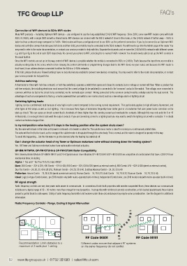
           RF signal strength
           Radio frequency controls use very low-power radio waves to communicate.  In conventional brick-built properties with wooden suspended floors, these devices can communicate
           reliably over a typical range of 20 – 30 metres: more than enough for most properties.  In properties with reinforced concrete construction, or foil-backed plasterboard, these feature
           present a partial block to radio waves.  Siting of radio frequency transmitter and receiver under these circumstances may require some consideration.  See the diagram for additional
           information:
           Radio Frequency Controls - Range, Coding & Signal Attenuation


              Rx


                                     Tx
                                                       RF Code 00001                    RF Code 00101

             Recommendation: Limit obstacles to a    Different codes ensure that adjacent RF systems
             maximum of 2 walls plus 1 ceiling       on the same frequency do not conflict


       52   www.tfc-group.co.uk     01732 351680     sales@tfc.uk.com

